

Most diagnostic automotive wiring diagrams are functional maps, not literal pictures of the harness. They show how a circuit is intended to operate.
Once you stop trying to absorb the entire page at once, even a complicated diagram becomes manageable. Identify the operating condition, find the power source, follow the control path, trace the load to ground, and turn each point in that path into a test.
This guide explains that process for working mechanics and independent repair shops.
Quick answer: To read an automotive wiring diagram, first confirm the exact vehicle and circuit. Read the legend and operating-state notes, then trace the functional path from power through protection, controls, connectors, the load, and ground. Use connector views and pinout tables to identify physical test points, and verify every critical pin and procedure against authoritative service information before probing.
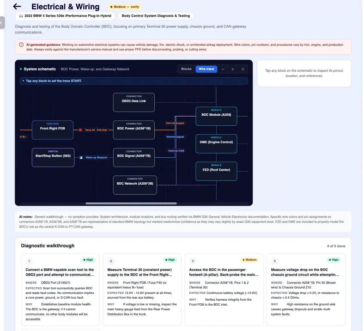
ARI's Electrical & Wiring Assistant combines an interactive circuit view with ordered diagnostic steps. AI-generated data still requires verification.
What type of diagram are you looking at?
Service information may place several different views next to one another. They answer different questions.
| View | What it shows | The question it answers |
|---|---|---|
| Schematic or circuit diagram | Electrical relationships using symbols and lines | How should this circuit operate? |
| Wiring or harness view | Routing, connectors, branches, and harness details | How are the wires connected or routed? |
| Connector view / pinout | Connector cavities and their functions | Which terminal should I test? |
| Component-location view | Physical position in the vehicle | Where is the relay, module, splice, ground, or connector? |
| Ground or splice distribution view | Shared points used by multiple circuits | Which other systems may be affected by this shared path? |
A schematic can show that a fuse is intended to feed a relay, but it may not show where that relay is mounted. A location view can lead you to the relay, but it may not explain which side of the relay coil is module-controlled. Effective diagnosis usually uses more than one view.
Step 1: Confirm the exact vehicle and affected system
Before tracing a line, verify:
- Year, make, and model
- Engine and drivetrain
- Trim or equipment package
- Production date or VIN split when relevant
- Market or region
- The specific system and symptom
The same model can use different modules, connectors, fuse assignments, wire colors, or control strategies. A correct-looking diagram for the wrong configuration can send a good technician in the wrong direction.
Start with the symptom, not the component you expect to replace. “Left low beam inoperative” defines a circuit. “Bad headlamp module” assumes the diagnosis is already complete.
Step 2: Read the legend and operating-state notes
Manufacturers do not all use the same symbols, abbreviations, or color codes. Read the diagram's legend before applying a convention learned from another brand.
Also note the state in which the circuit is drawn or tested. Common operating-state labels include:
- OFF — ignition or system off
- ACC — accessory position
- KOEO — key on, engine off
- KOER — key on, engine running
- Crank / START — starter-command state
A switch may be drawn in its normal rest position. A module output may be active only when a list of conditions is satisfied. If you do not reproduce the required state, a correct circuit can look faulty.
Step 3: Identify the circuit's building blocks
Most automotive circuits can be reduced to a small set of functions.
Power source
Usually the 12-volt battery or a power-distribution point. On hybrid and electric vehicles, do not assume a circuit is low voltage simply because a familiar symbol appears nearby.
Circuit protection
Fuses, fusible links, or circuit breakers protect the circuit. Record the rating and what else that protected feed supplies.
Controls
Switches, relay coils, control modules, drivers, and sensors determine when the circuit operates. Modern switches often send an input to a module rather than carrying load current directly.
Connectors and splices
Connectors join harness sections. Splices distribute one circuit to multiple branches. A single high-resistance splice or shared connector can create symptoms in several systems.
Load
The component that consumes electrical energy: a lamp, motor, solenoid, heater, relay coil, or module.
Ground
Ground or low-reference symbols identify a circuit return or reference path. Depending on the design, that path may run through the chassis, engine, or a module. The symbol does not prove that the physical connection is clean, tight, or able to carry current.
Data bus
CAN and other network lines carry messages rather than conventional load current. Network diagnosis requires the correct topology, test method, and service procedure.
Step 4: Trace the functional path—not every line on the page
Isolate the circuit you need. Then trace it in this order:
- Where does power enter?
- What protects the circuit?
- What conditions or controls allow it to operate?
- Which connectors, splices, or modules sit in the path?
- What is the load?
- How does current return to ground?
If the diagram spans several pages, note every continuation marker or cross-reference. Do not mentally jump across a missing page.
For a complex module-controlled circuit, trace two paths separately:
- The load path, which carries the working current
- The control path, which commands the relay, driver, or module
The load can have perfect power and ground while the control signal is absent. The switch input can be correct while the module driver or load path has failed. Separating the two prevents random parts replacement.
A simple circuit-tracing example
Consider this fictional, simplified low-beam circuit. The identifiers are examples only and do not belong to a real vehicle.
Load path:
Battery → fuse F1 → relay contacts → connector C1, cavity 4 → left low-beam lamp → ground G1
Control path:
Ignition feed → lighting-switch input → body-control-module command → relay-coil circuit
The symptom is: the left low beam is inoperative, while the right low beam works.
A logical test sequence might be:
- Confirm the complaint and required operating state.
- Check whether the fuse is powered on both sides under the commanded condition.
- Confirm the relay is being commanded and its contacts supply the load path.
- Compare voltage at the left lamp feed with the operating right side.
- Load-test or voltage-drop test the lamp ground path.
- If voltage is missing, move upstream to connector C1 and then toward the relay.
- If voltage and ground are present under load, evaluate the lamp and terminal fit.
The diagram does not tell you to replace the lamp. It tells you where the possible failure points are and in what order they can be isolated.
Step 5: Read wire labels carefully
A wire label can include:
- Circuit identifier
- Color and tracer color
- Wire size or gauge
- Connector or splice reference
- Destination or continuation reference
Color abbreviations and the order used for base and tracer colors vary by manufacturer and information source. Never infer a color code from another brand's convention; use the legend for the exact diagram.
Use color as one identifier, not the only identifier. Confirm the connector, cavity, circuit function, and orientation before testing.
Step 6: Understand connector pinouts—and the mirrored-view trap
A useful connector pinout normally identifies:
- Connector name or ID
- Pin or cavity number
- Circuit function
- Wire color and sometimes size
- Terminal or expected-value information
- Physical component or connector location
The most common avoidable mistake is reading the connector from the wrong side.
Mating face versus harness side
- The mating face is the side that plugs into the connector's partner.
- The wire-entry or harness side is the rear where the conductors enter.
Service information may use labels such as terminal side, connector side, or harness side differently. Turning the connector around can make the cavity layout appear mirrored. Use the orientation drawing, latch position, keyway, and molded cavity marks rather than relying on a label or “upper left” alone.
Step 7: Turn the diagram into a written test plan
For each test point, write four things:
- Condition: What must be on, connected, or commanded?
- Location: Which connector and cavity will be tested?
- Expected result: What voltage, ground, signal, or state should be present?
- Decision: What will a pass or fail tell you to test next?
| Test point | Condition | Expected result | If the result is wrong |
|---|---|---|---|
| Fuse output | Circuit commanded on | System voltage | Move toward power feed or protection |
| Load feed | Circuit connected and active | Voltage appropriate to the circuit | Test upstream connector, relay, or driver |
| Ground side under load | Load operating | Minimal voltage drop per service information | Inspect ground path, connection, or terminal fit |
| Control input | Required switch state | Specified input or data state | Test switch/input circuit before condemning module |
Expected values must come from service information for that vehicle and circuit. The table describes a method, not universal specifications.
Why voltage-drop testing matters
An unloaded circuit can show battery voltage through a connection that cannot carry the required current. That is why continuity alone does not prove the circuit will operate under load.
Fluke's automotive voltage-drop guide explains that excessive resistance in wires and connectors can restrict current and that voltage drop must be measured while current is flowing. Follow the vehicle manufacturer's procedure and limits; module, network, sensor, and high-current circuits do not all tolerate the same test methods.
Common wiring-diagram mistakes
Using the wrong configuration
The diagram is technically correct—but for another engine, trim, market, or production split.
Ignoring the operating condition
The technician tests an inactive circuit and interprets the expected lack of output as a fault.
Treating a diagnostic trouble code as a failed-part verdict
A DTC identifies a detected condition or circuit problem. It does not prove the named component has failed. Power, ground, control, communication, wiring, and connector integrity still need testing.
Assuming wire colors are universal
They are not. Read the legend for the exact source.
Testing the mirrored connector cavity
The pinout shows the terminal face while the technician is looking at the harness side—or vice versa.
Checking voltage without loading the circuit
Available voltage at rest can disappear when the load is connected. Use the correct loaded test or voltage-drop method.
Ignoring shared grounds and splices
Multiple symptoms can be the clue that several circuits share one physical point.
Replacing the load before proving the circuit
Confirm power, ground, and control under the required condition before condemning a component.
What to look for in automotive wiring-diagram software
If your shop is comparing repair-information or diagnostic software—not software for designing a custom harness—look beyond the number of diagrams advertised.
- Exact vehicle, engine, trim, and option selection
- Clear source and coverage information
- Searchable circuits, components, connectors, splices, and grounds
- Wire colors, circuit labels, and operating states
- Connector pinouts and orientation views
- Component and connector locations
- Continuation links across multi-page circuits
- Interactive highlighting or wire tracing
- Diagnostic steps and expected readings
- Confidence or source transparency for generated information
- Fast access from the estimate or work order
- A usable phone, tablet, or shop-computer experience
The best tool reduces the distance between “I found the circuit” and “I know where and how to test it.”
How ARI helps mechanics work from diagram to diagnosis
ARI's Electrical & Wiring Assistant is included in ARI Pro. Open Labor Guides, select the vehicle and service, generate Parts & Labor, and then choose Electrical & Wiring. It can generate a vehicle-specific schematic, connector pinouts, component locations, and an ordered diagnostic walkthrough. Wire-Trace mode can highlight a path between components, while confidence indicators and a sources panel provide context for the generated result.
The wiring tools sit alongside ARI's AI Labor Guides and Estimates, so repair information can stay close to estimates and Job Cards.
AI-generated electrical information is a diagnostic aid, not an OEM service manual. Verify critical pin assignments, wire colors, expected values, module procedures, and safety steps against official service information before testing or repair.
Safety comes before a faster diagnosis
- Follow the manufacturer's depowering, wait-time, lockout, and reconnect procedures.
- Use the correct meter, leads, adapters, fused jumpers, and personal protective equipment.
- Do not probe or apply power to SRS, pyrotechnic, network, or control-module circuits unless the authorized procedure explicitly calls for it.
- Protect terminals from spreading or damage; use approved back-probing or breakout methods.
- High-voltage hybrid and EV systems require specific training, PPE, test equipment, and procedures.
NHTSA advises that EV high-voltage systems should be serviced by qualified technicians with specialized training. Severe injury or death can result from unqualified high-voltage work.
Frequently asked questions
What is the easiest way to read an automotive wiring diagram?
Focus on one affected circuit. Confirm the vehicle and operating state, then trace power through circuit protection and controls to the load and ground. Use connectors and pinouts to turn that path into test points.
Should I trace a circuit from power or from ground?
Either direction can work, but a consistent source-to-load-to-ground method makes it easier to see the complete current path. For diagnosis, begin testing at the point most likely to divide the circuit efficiently based on the symptom.
What is a connector pinout diagram?
A pinout maps the cavities in a connector to circuit functions, wire colors, and sometimes expected values. Confirm whether it shows the mating face or the wire-entry side before identifying a pin.
Are automotive wire colors standardized?
No. Conventions and abbreviations vary by manufacturer and information provider. Always use the legend and vehicle-specific data.
Can a wiring diagram tell me which part is bad?
Not by itself. It shows circuit design and test points. Meter readings, scan data, operating conditions, visual inspection, and service procedures determine where the fault is.
Is continuity testing enough to diagnose automotive wiring?
Often no. A high-resistance connection may pass a low-current continuity test but fail under working load. Use the specified loaded or voltage-drop test when appropriate.
Can AI-generated wiring diagrams replace OEM information?
No. They can make the circuit easier to navigate and help organize a test plan, but safety-critical pins, procedures, specifications, and high-voltage information must be verified against authoritative OEM service documentation.
The bottom line
Reading an automotive wiring diagram is a process of reduction. Confirm the vehicle, isolate one circuit, understand its state, trace the functional path, identify the physical test points, and let each measurement determine the next step.
When the diagram becomes a test plan instead of a wall of lines, electrical diagnosis gets faster, safer, and much less dependent on guesswork.
See ARI's Electrical & Wiring Assistant in action, then verify every safety-critical pin, value, and procedure against authoritative service information for the vehicle.